Speech is generated by pumping air from the lung through the vocal tract consisting of throat, nose, mouth, palate, tongue, teeth and lips.
Human Vocal Tract. For the creation of nasal sounds, the nasal cavity can be coupled to the rest of the vocal tract by the soft palate.
In voiced sounds, the tense vocal chords are vibrating and the airflow gets modulated. The oscillation frequency of the vocal chords is called 'pitch'. The vocal tract colours the spectrum of the pulsating air flow in a sound-typical manner. In voiceless sounds, the vocal chords are loose and white-noise-like turbulences are formed at bottlenecks in the vocal tract. The remaining vocal tract colours the turbulating airflow more or less depending on the position of the bottleneck. Another type of voiceless sounds is created by an explosion-like opening of the vocal tract.
Speech Generation Model. The vocal-tract filter is time-variant. A simplified model integrates the glottis filter into the vocal tract filter.
The analogue speech signals are sampled and quantized. The sampling frequency is usually 8 kHz, and typical analogue/digital-converters have a linear resolution of 16 bit. With this so-called 'linear pulse code modulation' (linear PCM) we thus get a data stream of 128 kbit/s. The digitized speech is then compressed in order to reduce the bit rate.
Simple speech codecs as ITU-T G.711 encode each speech sample with only 8 instead of 16 bits by applying a quasi-logarithmic quantization curve (A-law in ETSI countries and mu-law in the US). The idea behind logarithmic companding is to provide a constant signal-to-noise ratio (SNR) independent from the signal level. This results in a data rate of 64 kbit/s. G.711 is the standard codec used in the Public Switched Telephone Network (PSTN) and Integrated Services Digital Network (ISDN) throughout the world.
Sampling and Logarithmic Quantization.
However, 64 kbit/s is much too much for mobile telephone networks and other applications as e.g. mass storage of speech signals. A further compression is therefore necessary. In contrast to general compression algorithms as e.g. ZIP, speech compression algorithms are lossy and exploit well-known statistical properties of speech and result thus in much higher compression rates.
One major property of speech is its correlation, i.e. successive samples of a speech signal are similar. This is depicted in the following figure:
German vowel /a/
The short-term correlation of successive speech samples has consequences for the short-term spectral envelopes. These spectral envelopes have a few local maxima, the so called 'formants' which correspond to resonance frequencies of the human vocal tract. Speech consists of a succession of sounds, the so-called phonemes. While speaking, humans continuously change the setting of their vocal tract in order to produce different resonance frequencies (formants) and therefore different sounds.
German vowel /a/: Spectral estimation of original signal (green), spectral estimation of predicted signal with 10-th order short-term predictor (red) and frequency response of a 10-th order speech model filter based on the predictor coefficients (blue). Four formants can easily be identified.
This (short-term) correlation can be used to estimate the current speech sample from past samples. This estimation is called 'prediction'. Because the prediction is done by a linear combination of (past) speech samples, it is called 'linear prediction'. The difference between the original and the estimated signal is called 'prediction error signal'. Ideally, all correlation is removed, i.e. the error signal is white noise. Only the error signal is conveyed to the receiver: It has less redundancy, therefore each bit carries more information. In other words: With less bits, we can transport the same amount of information, i.e. have the same speech quality.
The calculation of the prediction error signal corresponds to a linear filtering of the original speech signal: The speech signal is the filter input, and the error signal is the output. Main component of this filter is the (short-term) predictor. The goal of the filter is to 'whiten' the speech signal, i.e. to filter out the formants. That is why this filter is also called an 'inverse formant filter'.
LPC Filter.
While speaking, the formants continuously change. The short-term correlation thus also changes and the predictor must be adapted to the these changes. Thus, the predictor and the prediction error filter are adaptive filters whose parameters must be continuously estimated from the speech signal.
For those interested in details, here are the mathematics for the calculation of the filter coefficients:
Voiced sounds as e.g. vowels have a periodic structure, i.e. their signal form repeats itself after some milliseconds, the so-called pitch period TP. Its reciprocal value fP=1/TP is called pitch frequency. So there is also correlation between distant samples in voiced sounds.
German vowel /a/. Listen how this vowel sounds.
This long-time correlation is exploited for bit-rate reduction with a so-called long-term predictor (also called pitch predictor).
Also the pitch frequency is no constant. In general, female speakers have higher pitch than male speakers. Furthermore, the pitch frequency varies in a speaker-typical manner. In addition to that there are voice-less sounds as consonants which do not have a periodic structure at all, and mixed sounds with voice-less and voiced components also exist. Thus, also the pitch predictor must be implemented as an adaptive filter, and the pitch period and the pitch gain must be continuously estimated from the speech signal.
A useful representation of the speech signal is the so-called spectrogram, which shows the signal's power distribution with respect to time and frequency. The idea is to calculate the (short-term) power spectral densities (this gives the power and frequency information) of successive (this gives the time information) fragments of the signal. Usually, the time is printed on the x-scale of a spectrogram and the frequency on the y-scale. The power is coded in the color, for example red means high power and blue low power. The spectrogram in the following figure shows all the so far discussed speech characteristics. The upper picture is the waveform, and the lower the corresponding spectrogram. We will use exactly this speech signal later as input for our example codecs.
Waveform and corresponding Spectrogram
Only the parameters of the inverse format filter and the inverse pitch filter plus the error signal are transmitted to the receiver. The receiver constructs the inverse filters, i.e. a pitch filter and a formant filter, and reconstructs the speech signal by inverse filtering of the error signal. This coding structure is known as 'Adaptive Predictive Coding' (APC).
Adaptive Predictive Coding
APC is the basis for a variety of so-called waveform speech codecs which try to preserve the waveform of the speech signal. The idea is not to convey the error signal completely: Only an equivalent version is transferred, or a version carrying the main information. Thus we are saving bits:
Modern algorithms which are used in digital mobile networks as GSM or UMTS have a limited storage of potential prediction error signals (the stochastic codebook), and the index of the best-fitting signal is transferred to the receiver. The decoder has the same codebook available and can retrieve the best-fitting error signal with the index. In contrast to a full-size error signal, such an index needs only a few bits. Which of the potential error signals is the best one? To answer this question, each prediction error signal is already vocal-tract filtered in the coder and the thus synthesized speech signal is compared to the original speech signal by applying an error measure, e.g. the mean square error. The prediction error signal which minimizes the error measure is chosen. This procedure is called 'analysis-by-synthesis'. Mathematically, a vector quantization of the original speech segment is performed.
CELP Principle: Analysis-by-Synthesis. The best codebook vector is determined and afterwards the corresponding best gain value is calculated.
Here's full-functional MatLab Code simulating such a basic CELP Codec:
You may listen to a male speech sample coded and decoded with this CELP codec:
The parameter settings used in this example resulted in a bit rate of only 1 kbit/s. However, the speech quality is inferior: Although intelligible, the codec sounds artificial and lacks naturalness. This is because voiced (periodic) speech frames are no good reproduced. This can be improved by performing an APC-like pitch analysis first. The calculated LTP delay and LTP gain values are used for inducing a pitch structure into the stochastic codebook vectors prior to the analysis-by-synthesis. This idea is realized in the next example:
Open-Loop CELP Principle: Analysis-by-Synthesis. Note that the decoder is fully included in the coder. Note also that a main part of the structure resembles an APC decoder.
Here's full-functional MatLab Code simulating this basic Open-Loop CELP Codec:
You may also listen to a male speech sample coded and decoded with this Open-Loop CELP codec:
Here we get a fairly good speech quality with parameter settings resulting in a bit rate of 5.4 kbit/s. If you have access to MatLab, you can change parameter settings and observe how the speech quality improves or deteriorates. Note that the pitch determination is done before the analysis-by-synthesis, so we do not know if the calculated pitch parameters are really optimal with respect to the final error measure which is calculated after vocal-tract filtering: There might be better LTP delay and gain values which - after vocal-tract filtering - result in a better approximation of the original speech signal. Because the LTP calculation is not included into the analysis-by-synthesis, this structure is called 'Open-Loop'.
The LTP analysis can also be included into the Analysis-by-Synthesis resulting in an even better reproduction of voiced frames, especially for small LTP delay values which are typical for female speakers. Such a structure is called 'Closed-Loop'. The next example shows a basic Closed-Loop CELP codec:
Closed-Loop CELP Principle: LTP included in Analysis-by-Synthesis.
Here's again full-functional MatLab Code simulating a basic Closed-Loop CELP Codec:
You may listen to a male speech sample coded and decoded with this Closed-loop CELP codec:
First, the optimal adaptive excitation is determined, and then in a second step, the optimal stochastic excitation for minimizing the remaining error. Again, we get a quite good speech quality with parameter settings resulting in a bit rate of 5.4 kbit/s. With MatLab, change again parameter settings and observe how the speech quality improves or deteriorates.
Now you know how a Closed-loop CELP which is the basis for state-of-the-art speech codecs as ITU-T G.726.1, ITU-T G.729, ETSI GSM Enhanced Fullrate Codec (EFR) etc. works! All these mentioned advanced codecs use this concept, and more or less they differ only in the implementation and some tricks leading to a somehow better speech quality:
The analysis-by-synthesis is computationally very expensive, so a lot of effort has been spent in the past to reduce the computational complexity of CELP (the code shown on this page is intentionally not optimized concerning MIPs and MFLOPs since I want to show the principles and concepts not bothering with implementation details). Most of the ideas concern the stochastic codebook: By using special structures, the computational cost of the vocal-tract filtering can be greatly simplified:
The CELP codecs shown here so far still do not sound good enough. Many ideas resulted in a considerable improvement of the speech quality:
UMTS (Universal Mobile Telecommunications System) networks will supplement and finally replace the GSM networks. UMTS will utilize the AMR codec. AMR offers several bitrates and can thus be adapted to the current channel conditions. AMR is nothing special, it is just an algebraic CELP codec as described above. Different parameter settings lead to different speech qualities and bitrates.
The next step on our way starting from PCM and leading to Closed-Loop CELP is to transmit an excitation signal not at all but only to convey some parameters describing it, e.g. its power. Such an algorithm produces really artificial speech and is known as a 'Vocoder' (Voice Coder).
LPC Vocoder Principle: Only parameters are conveyed to the decoder.
Here's again full-functional MatLab Code simulating a basic LPC Vocoder:
This codec contains a simple classifier which decides whether the current frame is a silence, voiceless or voiced frame: The signal level determines if it is a silence frame or not, and if it is non-silence, the average zero-crossing rate determines if it is voiceless or voiced (in voiceless frames, there are more zero-crossings). The classifier result is feeded into a state-machine which takes the final decision whether the frame shall be treated as silence, voiced or voiceless (the idea is too smooth out changes from voiced/voiceless to silence). Mixed voiced/voiceless excitations are not supported by this implementation. In voiceless frames, only the mean signal amplitude and the predictor coefficients are calculated and conveyed to the decoder. In voiced frames, also the pitch lag is estimated (with a very simple block autocorrelation approach) and conveyed. The decoder creates an excitation signal from the silence (just zeroes), voiceless (just random noise) and voiced (just 1-pulses in a distance corresponding to the current estimated pitch lag) information and filters it with the adaptive vocal tract filter constructed with the transmitted LPC predictor coefficients.
You may listen to a male speech sample coded and decoded with this LPC Vocoder:
With this really simple structure which has much room for improvements, we already get a not too poor speech quality with parameter settings resulting in a maximum bit rate (in voiced frames) as low as 2.5 kbit/s. With MatLab, change again parameter settings and observe how the speech quality improves or deteriorates.
Apart from waveform codecs there are also codecs which are operating in the frequency domain. The speech signal is dismantled into its spectral components which are transmitted in coded form to the receiver. The receiver reconstructs the speech signal from the spectral information. In the frequency domain, certain properties of the human ear can be efficiently exploited for psychoacoustics-based data compression, for example masking effects: The perception of weak signals can be suppressed by loud signals which are presented at the same time (or even shortly before or after). But signal components which cannot be heard are irrelevant and need not be transmitted to the receiver. Modern audio coding algorithms as MP3, DCC or Mini-Disc also operate in the frequency domain and exploit these masking effects. Frequency-domain coding is however not very popular for the compression of narrowband speech as used in telephone networks.
P. Vary, U. Heute, W. Hess, Digitale Sprachsignalverarbeitung, B.G. Teubner Stuttgart, 1998.
H. Carl, Untersuchung verschiedener Methoden der Sprachkodierung und eine Anwendung zur Bandbreitenvergrößerung von Schmalband-Sprachsignalen, Shaker Verlag, 1994.
N. Görtz, Aufwandsarme Qualitätsverbesserungen bei der gestörten Übertragung codierter Sprachsignale, Shaker Verlag, 1999.
L. R. Rabiner and R. W. Schafer, Digital Processing of Speech Signals.
B. S. Atal, V. Cuperman, and A. Gersho, Speech and Audio Coding for Wireless and Network Applications.
B. S. Atal, V. Cuperman, and A. Gersho, Advances in Speech Coding.
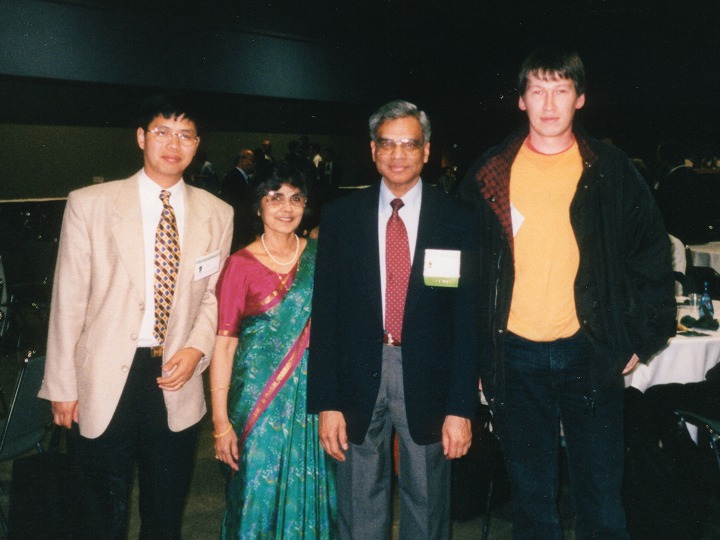
At ICASSP'98: Bishnu S. Atal (second from right), the inventor of CELP, and me (right).